Understanding yield point: Effect on pressure surges critical to managing deep, difficult MPD wells
By Shifeng Tian, George H Medley and Charles R “Rick” Stone, Signa Engineering
Managed Pressure Drilling (MPD) is often used to drill formations that have a narrow window between formation pore pressure and fracture pressure. Applying variations of MPD maintains the wellbore pressure within the narrow window during the entire operation process, including drilling, connections, tripping, etc. But accurate pore pressure and fracture pressure information may not be available. To prevent formation influx or lost-circulation problems, wellbore pressures should be kept as constant as possible during the entire drilling process.
Rheologic properties of drilling fluids play an important role in managing wellbore pressure. Most drilling fluids currently used in the field, including water-based mud (WBM), synthetic-based mud (SBM) and oil-based mud (OBM), have a non-zero yield point (YP). A non-zero YP causes a sudden pressure change when the fluid starts to move or when it’s about to stop moving. It also causes a sudden change of the surge or swab pressure when the drillstring starts to move up/down during drilling or tripping, regardless of how slow the pipe moves.
This creates problems for keeping the wellbore pressure constant. An understanding of the effects of mud rheologic properties, especially YP, is essential to the success of any MPD project.
WHAT IS YIELD POINT?

Figure 1: Yield point of Herschel-Bulkley model is the shear stress at zero shear rate.
Yield point is the term used to measure the intersection of the shear stress axis by the relation between shear stress (t) and shear rate (g) of a fluid (i.e., YP is the shear stress at zero shear rate, as shown in Figure 1).
Some fluids, such as Newtonian fluids and Power-Law fluids, intersect the shear stress axis at the origin point. The value of YP for these fluids is zero. However, most drilling fluids are non-Newtonian and have a non-zero YP. The term YP was introduced with the Bingham Plastic model. It later was used in conjunction with the Herschel-Bulkley model, also referred to as the Modified Power-Law model.
Historically, YP has been estimated by Equations 1 and 2:
μp = q600 – q300 (1)
YP = q300 – μp (2)
where q600 and q300 are the Fann viscometer readings at 600 rpm and 300 rpm respectively.
With these equations, only two of the six readings from the Fann viscometer are used to estimate the value of YP. This approximation was necessitated by limitations of early viscometers in the field and by the need for a quick and easy estimation of rheology. Unfortunately, this estimation is usually grossly overestimated. Because YP is defined as the shear stress at a zero shear rate, it might be better estimated using low shear rate readings from the Fann viscometer (readings at low rpm). When estimated correctly, the value of YP should be slightly less than the 3 rpm shear rate reading.
The Herschel-Bulkley model is generally accepted as the best representation of drilling fluids. It is mathematically represented by Equation 3:
t = YP + μgn (3)
As indicated by Equation 3, in order for the fluid to move (shear rate, g, greater than zero), shear stress, t, must be greater than YP. This is why YP causes a sudden pressure change when the fluid starts to move or is about to stop moving. In contrast to general fluid concepts, when shear stress is less than or equal to YP, the fluid actually behaves like a solid. During an operation, any activity that changes the fluid status between static and moving will cause pressure to change abruptly if the fluid has a non-zero YP.
YP EFFECT ON CIRCULATION
An example well is used to demonstrate the effects of YP. A 16.8 ppg SBM is selected as the circulating fluid. Viscometer readings for this mud are listed in Table 1. When using Equations 1 and 2, the estimated value of μp will be 34 cp (= 97 – 63), and YP will be 29 lbf/100ft2 (= 63 – 34). The estimated value of YP by Equations 1 and 2 is obviously too high. As listed in Table 1, the viscometer reading, which is the shear stress in lbf/100ft2, at 3 rpm (shear rate equals rpm multiplied by 1.7) is 16. YP (the shear stress at zero shear rate) can’t be greater than the shear stress at 3 rpm. The overestimation is a result of using only two viscometer readings. A more general algorithm that estimates YP by using all six viscometer readings is available in the extended-reach drilling simulator (ERDS) program. If all six readings are included, the estimated YP should be 14.9 lbf/100ft2, which is lower than the shear stress at 3 rpm.

Figure 2 shows how the bottomhole pressure (BHP) changes during ramping up or shutting down the pump. The sudden BHP change at zero circulating rate is caused by the 14.9 lbf/100ft2 YP. When there is no circulation, the hydrostatic pressure at bottomhole is about 17,448 psig. As Figure 2 indicates, the fluid in the wellbore annulus will not move until the BHP is increased to 17,668 psig. In this case, the pressure change at bottomhole caused by the 14.9 lbf/100ft2 YP is about 220 psi (i.e., the difference in bottomhole pressure between static and barely circulating fluid).
The blue curve in Figure 3 is obtained by setting the YP to zero for comparison. With a zero YP, there is no abrupt pressure change at the start of pumping. It also indicates that the effect of YP on BHP is gradually reduced with increasing pump rate – the BHP difference between these two cases is 220 psi at the start of pumping while it is less than 150 psi at a pump rate of 400 gpm. The abrupt slope change of the BHP curve in both Figures 2 and 3 is due to the flow regime change between Laminar flow and Turbulent flow. Comparison between Figures 2 and 3 shows that the non-zero YP also causes the transition between Laminar flow and Turbulent flow to occur at a larger circulating rate.
DURING CONNECTIONS

Figure 2 shows the pressure change caused by YP as the pump starts or stops.
Maintaining wellbore pressure as constant as possible during the MPD process is often desirable. However, frictional pressure during circulation will disappear when stopping the pump to make a connection. The common practice in MPD operations is to add or increase surface choke pressure when making connections to compensate for the disappearance of the frictional pressure.
Adding or increasing surface choke pressures to offset the disappearance of frictional pressure requires a carefully designed pump and choke operating schedule and good cooperation between the pump and choke operators. During shut-down of the rig pump, the circulation rate must be decreased step by step, while the choke pressure must be increased accordingly at each step to offset the decrease of frictional pressure due to circulation rate reduction.
To keep the wellbore annulus pressure during the connection the same as during drilling, the total increase of choke pressure when the pump is completely shut down should equal the total annular frictional pressure loss plus the total weight of cuttings in the annulus during drilling.
In practice, this is simplified by assuming the cuttings concentration remains the same during the connection as when drilling. In that case, the total increase of choke pressure when the pump is completely shut down should be equal to the total annular frictional pressure loss.

Figure 3: With a zero YP, there is no pressure change at pump start.
A reverse incremental increase in pump circulation rate corresponding to an incremental decrease in choke pressure should be followed during the resumption of circulation after the connection is made.
Table 2 shows one of the operating schedules for the example well. The second column in the table indicates that the pump rate is reduced by 20 gpm at each step, while the last column of the table shows the choke pressure that needs to be applied at each step in order to maintain BHP (column 4) the same as when drilling. Table 2 shows that the increment of the choke pressure change at the last step is much larger than at any of the previous steps (the increment of the choke pressure change at the last step is about 220 psi).
This is due to the fact that the 14.9 lbf/100ft2 YP causes about 220 psi bottomhole pressure change when the pump is completely shut down. The total choke pressure required to maintain constant BHP when the pump is completely shut down in this case is 399 psi.
Table 3 shows a similar operating schedule but with YP set to zero. The pump rate is also reduced by 20 gpm at each step. The increase of choke pressure required to maintain constant BHP at each step in the last several steps is almost constant. The total choke pressure required to maintain constant BHP when the pump is completely shut off is 322 psi in this case.
DURING TRIPPING

Tripping the drillstring causes surge pressure when lowering the drillstring into the well and swab pressure when pulling the drillstring out of the well. Surge pressure increases BHP while swab pressure reduces BHP. In a deep or extended-reach well, tripping could cause the wellbore pressure to exceed the operating window. The common practice to reduce surge or swab pressure is to decrease tripping speed. While lowering tripping speed does reduce surge or swab pressure, the value of YP in some cases is also important to consider.

Figure 4 displays the surge and swab pressure caused by tripping at different speeds in the example well. The dark green curve at the middle of the figure is the profile of the hydrostatic pressure. The three curves to the right side of the hydrostatic pressure are surge pressures at tripping speeds of 0.01 ft/sec (0.6 fpm), 1 ft/sec (60 fpm), and 2 ft/sec (120 fpm), respectively. The three curves to the left side of the hydrostatic pressure are swab pressures at the same three tripping speeds.
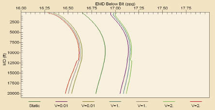
Figure 4: Surge/swab pressure while tripping at different speeds in the example well.
As Figure 4 shows, a low tripping speed does reduce the surge or swab pressure during tripping (i.e., makes the wellbore pressure during tripping closer to the hydrostatic pressure). However, even at a tripping speed of 0.01 ft/sec, the pressure profile is not close to the hydrostatic pressure profile. This is due to the fact that a non-zero YP causes a sudden pressure change (surge or swab) whenever the drillstring starts to move – no matter how slow it moves.
For comparison, Figure 5 displays the surge and swab pressure at the same tripping speeds with YP set to zero. Surge and swab pressure caused by a tripping speed of 0.01 ft/sec with zero YP almost overlap the hydrostatic pressure profile in Figure 5.

Figure 5: Surge/swab pressure with zero YP, compared with Figure 4.
YP VS GEL STRENGTH
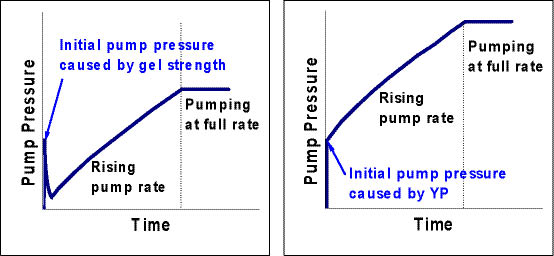
YP is similar to mud gel strength in causing a sudden pressure change at the start of pumping. However, the major difference between YP and gel strength in term of hydraulics is that gel strength will not exist once the fluid is moving and the gel has been broken, while the effects of YP will not disappear when the fluid is moving. Figure 6 shows the rapid pump pressure change caused by gel strength and YP at the beginning of pumping. As indicated by the left plot in Figure 6, the pressure surge caused by gel strength at the start of pumping disappears quickly, while the pressure surge caused by YP (right plot) does not.
Gel strength is a status-dependent property of a mud. Its value depends on how well the gel is formed. In the field, the pressure surge caused by mud gel strength can be avoided by rotating the drillstring to break the gel before the start of pumping. YP is not a status-dependent property of a mud. The value of YP may vary with temperature and pressure. However, the pressure change at the start/stop of pumping can’t be avoided with a non-zero YP by any mechanical means.
SUMMARY
A non-zero YP causes a sudden pressure change when fluid starts to move or is about to stop moving. It also causes a sudden BHP change when the drillstring starts to move up/down during drilling or tripping, regardless of how slow the pipe moves. Low YP fluids help to reduce the pressure change. Rheology model parameters should be determined by readings at all six viscometer speeds. Rheology parameters determined using only two readings may cause inaccurate wellbore pressure prediction.
By Shifeng Tian, George H Medley and Charles R “Rick” Stone, Signa Engineering
MANAGED PRESSURE DRILLING (MPD) is often used to drill formations that have a narrow window between formation pore pressure and fracture pressure. Applying variations of MPD maintains the wellbore pressure within the narrow window during the entire operation process, including drilling, connections, tripping, etc. But accurate pore pressure and fracture pressure information may not be available. To prevent formation influx or lost-circulation problems, wellbore pressures should be kept as constant as possible during the entire drilling process.
Rheologic properties of drilling fluids play an important role in managing wellbore pressure. Most drilling fluids currently used in the field, including water-based mud (WBM), synthetic-based mud (SBM) and oil-based mud (OBM), have a non-zero yield point (YP). A non-zero YP causes a sudden pressure change when the fluid starts to move or when it’s about to stop moving. It also causes a sudden change of the surge or swab pressure when the drillstring starts to move up/down during drilling or tripping, regardless of how slow the pipe moves.
This creates problems for keeping the wellbore pressure constant. An understanding of the effects of mud rheologic properties, especially YP, is essential to the success of any MPD project.
WHAT IS YIELD POINT?
Figure 1: Yield point of Herschel-Bulkley model is the shear stress at zero shear rate.
Yield point is the term used to measure the intersection of the shear stress axis by the relation between shear stress (t) and shear rate (g) of a fluid (i.e., YP is the shear stress at zero shear rate, as shown in Figure 1).
Some fluids, such as Newtonian fluids and Power-Law fluids, intersect the shear stress axis at the origin point. The value of YP for these fluids is zero. However, most drilling fluids are non-Newtonian and have a non-zero YP. The term YP was introduced with the Bingham Plastic model. It later was used in conjunction with the Herschel-Bulkley model, also referred to as the Modified Power-Law model.
Historically, YP has been estimated by Equations 1 and 2:
μp = q600 – q300 (1)
YP = q300 – μp (2)
where q600 and q300 are the Fann viscometer readings at 600 rpm and 300 rpm respectively.
With these equations, only two of the six readings from the Fann viscometer are used to estimate the value of YP. This approximation was necessitated by limitations of early viscometers in the field and by the need for a quick and easy estimation of rheology. Unfortunately, this estimation is usually grossly overestimated. Because YP is defined as the shear stress at a zero shear rate, it might be better estimated using low shear rate readings from the Fann viscometer (readings at low rpm). When estimated correctly, the value of YP should be slightly less than the 3 rpm shear rate reading.
The Herschel-Bulkley model is generally accepted as the best representation of drilling fluids. It is mathematically represented by Equation 3:
t = YP + μgn (3)
As indicated by Equation 3, in order for the fluid to move (shear rate, g, greater than zero), shear stress, t, must be greater than YP. This is why YP causes a sudden pressure change when the fluid starts to move or is about to stop moving. In contrast to general fluid concepts, when shear stress is less than or equal to YP, the fluid actually behaves like a solid. During an operation, any activity that changes the fluid status between static and moving will cause pressure to change abruptly if the fluid has a non-zero YP.
YP EFFECT ON CIRCULATION
An example well is used to demonstrate the effects of YP. A 16.8 ppg SBM is selected as the circulating fluid. Viscometer readings for this mud are listed in Table 1. When using Equations 1 and 2, the estimated value of μp will be 34 cp (= 97 – 63), and YP will be 29 lbf/100ft2 (= 63 – 34). The estimated value of YP by Equations 1 and 2 is obviously too high. As listed in Table 1, the viscometer reading, which is the shear stress in lbf/100ft2, at 3 rpm (shear rate equals rpm multiplied by 1.7) is 16. YP (the shear stress at zero shear rate) can’t be greater than the shear stress at 3 rpm. The overestimation is a result of using only two viscometer readings. A more general algorithm that estimates YP by using all six viscometer readings is available in the extended-reach drilling simulator (ERDS) program. If all six readings are included, the estimated YP should be 14.9 lbf/100ft2, which is lower than the shear stress at 3 rpm.
Figure 2 shows how the bottomhole pressure (BHP) changes during ramping up or shutting down the pump. The sudden BHP change at zero circulating rate is caused by the 14.9 lbf/100ft2 YP. When there is no circulation, the hydrostatic pressure at bottomhole is about 17,448 psig. As Figure 2 indicates, the fluid in the wellbore annulus will not move until the BHP is increased to 17,668 psig. In this case, the pressure change at bottomhole caused by the 14.9 lbf/100ft2 YP is about 220 psi (i.e., the difference in bottomhole pressure between static and barely circulating fluid).
The blue curve in Figure 3 is obtained by setting the YP to zero for comparison. With a zero YP, there is no abrupt pressure change at the start of pumping. It also indicates that the effect of YP on BHP is gradually reduced with increasing pump rate – the BHP difference between these two cases is 220 psi at the start of pumping while it is less than 150 psi at a pump rate of 400 gpm. The abrupt slope change of the BHP curve in both Figures 2 and 3 is due to the flow regime change between Laminar flow and Turbulent flow. Comparison between Figures 2 and 3 shows that the non-zero YP also causes the transition between Laminar flow and Turbulent flow to occur at a larger circulating rate.
DURING CONNECTIONS
Figure 2 shows the pressure change caused by YP as the pump starts or stops.
Maintaining wellbore pressure as constant as possible during the MPD process is often desirable. However, frictional pressure during circulation will disappear when stopping the pump to make a connection. The common practice in MPD operations is to add or increase surface choke pressure when making connections to compensate for the disappearance of the frictional pressure.
Adding or increasing surface choke pressures to offset the disappearance of frictional pressure requires a carefully designed pump and choke operating schedule and good cooperation between the pump and choke operators. During shut-down of the rig pump, the circulation rate must be decreased step by step, while the choke pressure must be increased accordingly at each step to offset the decrease of frictional pressure due to circulation rate reduction.
To keep the wellbore annulus pressure during the connection the same as during drilling, the total increase of choke pressure when the pump is completely shut down should equal the total annular frictional pressure loss plus the total weight of cuttings in the annulus during drilling.
In practice, this is simplified by assuming the cuttings concentration remains the same during the connection as when drilling. In that case, the total increase of choke pressure when the pump is completely shut down should be equal to the total annular frictional pressure loss.
Figure 3: With a zero YP, there is no pressure change at pump start.
A reverse incremental increase in pump circulation rate corresponding to an incremental decrease in choke pressure should be followed during the resumption of circulation after the connection is made.
Table 2 shows one of the operating schedules for the example well. The second column in the table indicates that the pump rate is reduced by 20 gpm at each step, while the last column of the table shows the choke pressure that needs to be applied at each step in order to maintain BHP (column 4) the same as when drilling. Table 2 shows that the increment of the choke pressure change at the last step is much larger than at any of the previous steps (the increment of the choke pressure change at the last step is about 220 psi).
This is due to the fact that the 14.9 lbf/100ft2 YP causes about 220 psi bottomhole pressure change when the pump is completely shut down. The total choke pressure required to maintain constant BHP when the pump is completely shut down in this case is 399 psi.
Table 3 shows a similar operating schedule but with YP set to zero. The pump rate is also reduced by 20 gpm at each step. The increase of choke pressure required to maintain constant BHP at each step in the last several steps is almost constant. The total choke pressure required to maintain constant BHP when the pump is completely shut off is 322 psi in this case.
DURING TRIPPING
Tripping the drillstring causes surge pressure when lowering the drillstring into the well and swab pressure when pulling the drillstring out of the well. Surge pressure increases BHP while swab pressure reduces BHP. In a deep or extended-reach well, tripping could cause the wellbore pressure to exceed the operating window. The common practice to reduce surge or swab pressure is to decrease tripping speed. While lowering tripping speed does reduce surge or swab pressure, the value of YP in some cases is also important to consider.
Figure 4 displays the surge and swab pressure caused by tripping at different speeds in the example well. The dark green curve at the middle of the figure is the profile of the hydrostatic pressure. The three curves to the right side of the hydrostatic pressure are surge pressures at tripping speeds of 0.01 ft/sec (0.6 fpm), 1 ft/sec (60 fpm), and 2 ft/sec (120 fpm), respectively. The three curves to the left side of the hydrostatic pressure are swab pressures at the same three tripping speeds.
Figure 4: Surge/swab pressure while tripping at different speeds in the example well.
As Figure 4 shows, a low tripping speed does reduce the surge or swab pressure during tripping (i.e., makes the wellbore pressure during tripping closer to the hydrostatic pressure). However, even at a tripping speed of 0.01 ft/sec, the pressure profile is not close to the hydrostatic pressure profile. This is due to the fact that a non-zero YP causes a sudden pressure change (surge or swab) whenever the drillstring starts to move – no matter how slow it moves.
For comparison, Figure 5 displays the surge and swab pressure at the same tripping speeds with YP set to zero. Surge and swab pressure caused by a tripping speed of 0.01 ft/sec with zero YP almost overlap the hydrostatic pressure profile in Figure 5.
Figure 5: Surge/swab pressure with zero YP, compared with Figure 4.
YP VS GEL STRENGTH
YP is similar to mud gel strength in causing a sudden pressure change at the start of pumping. However, the major difference between YP and gel strength in term of hydraulics is that gel strength will not exist once the fluid is moving and the gel has been broken, while the effects of YP will not disappear when the fluid is moving. Figure 6 shows the rapid pump pressure change caused by gel strength and YP at the beginning of pumping. As indicated by the left plot in Figure 6, the pressure surge caused by gel strength at the start of pumping disappears quickly, while the pressure surge caused by YP (right plot) does not.
Gel strength is a status-dependent property of a mud. Its value depends on how well the gel is formed. In the field, the pressure surge caused by mud gel strength can be avoided by rotating the drillstring to break the gel before the start of pumping. YP is not a status-dependent property of a mud. The value of YP may vary with temperature and pressure. However, the pressure change at the start/stop of pumping can’t be avoided with a non-zero YP by any mechanical means.
SUMMARY
A non-zero YP causes a sudden pressure change when fluid starts to move or is about to stop moving. It also causes a sudden BHP change when the drillstring starts to move up/down during drilling or tripping, regardless of how slow the pipe moves. Low YP fluids help to reduce the pressure change. Rheology model parameters should be determined by readings at all six viscometer speeds. Rheology parameters determined using only two readings may cause inaccurate wellbore pressure prediction.
Pressure surge caused by YP must be accounted for during drilling, making drillstring connections, and tripping, especially in deep wells and when the operating pressure window is narrow.
Mud gel strength also causes a pressure change at the start of pumping. The pressure surge caused by gel strength disappears quickly, while the pressure surge caused by YP does not.


i am foreman i like more information about mud every thing or help me for take course any where i am ready any time i waiting your response as soon as possible
thank’s