Study analyzes response of deepwater riser with suspended BOP
Environmental effects, drilling vessel motions evaluated to determine maximum allowable operational conditions
By C.K. Morooka and J.R.P. Mendes, University of Campinas; K. Miura, Cenpes – Petrobras

Worldwide petroleum demand induces the search for new offshore oil and gas reserves in deeper and deeper waters. In this scenario, offshore drilling is carried out in water depths up to 3,000 m (nearly 10,000 ft). Access to the sea floor for new well construction is currently achieved through the marine riser system, installing a BOP on the subsea wellhead.
When the subsea wellbore construction is finished, the riser column, including the BOP, is normally retrieved to the deck of the drilling vessel before mobilizing the drilling vessel to a new drill site to begin the next well. In this operation, the marine riser column is retrieved by disconnecting every riser joint, one by one, to the rig deck. It can be a time-consuming operation requiring several hours, sometimes days.
Moreover, when the drilling vessel reaches the next drill site for a new well construction, more time will be needed again before the rig vessel can initiate drilling of the new well. A time-saving process, which can also be a cost-saving alternative, would be to move the floating rig, retrieving only few riser joints and moving the drilling vessel to a new site. Moving the BOP suspended by the riser has been considered in the past. There have been published analyses of the disconnected riser when suspended from a drifting vessel, with an emphasis on the management of the deflected shape and reaction of shear loads into the vessel. Reports also have been presented on the moving of the suspended BOP by a marine riser system in soft and hard hangoff modes and system responses, as well as survivability.
This article focuses on a study analyzing marine riser response with a suspended BOP in deepwater. Effects of the environment, as well as the drilling vessel’s motions, were evaluated to determine maximum allowable operational conditions with regards to vessel forward speed. The article also outlines a procedure to evaluate riser behavior under several environmental loading conditions during the BOP-deployed move in order to delimit environment conditions where the operations can be carried out.

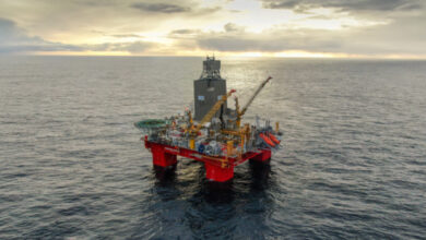
A time domain numerical simulation model was employed on a computer to simulate riser dynamic behavior. Calculations were based on the finite element representation of the riser column. It accounted for riser axial tension, environmental loads and pressure effects due to internal and external fluid pressure. Sea current, waves, vessel motions and vessel advancing speed also were considered. Figure 1 shows this operation.
Riser dynamic behavior and the environment
The dynamic behavior of the riser is represented in Equation 1:
![]()
[M] is the mass matrix, [B] is the viscous damping, [K] is the stiffness matrix, and x, and are, respectively, riser displacement, velocity and acceleration vectors in the in-line plane.
F is the hydrodynamic force, vector estimated from the Morison formulations, as shown in Equation 2:
![]()
In Equation 2, AI=πD2ρ/4, AD=½ ρD, CD is the hydrodynamic drag force coefficient, CA is the added mass coefficient, and u and are water particle velocity and acceleration, respectively. D is the riser outer diameter, and ρ is the density of external fluid.
Superposition of linear waves was considered, and time series of irregular sea states were obtained by the sum of regular wave components in Equation 3:
![]()
ζ(t) is the instantaneous wave elevation, ζan, kn, ωn and εn are, respectively, wave amplitude, wave number, frequency and phase angle of the nth wave component.
The Pierson-Moskowitz (PM) wave spectrum was considered for waves and used in the analysis. Then, each sea state can be estimated from Equation 4:
![]()
Sζ(ω) is the wave energy density at a given frequency ω, H1/3 is the significant wave height and TZ is the mean zero-crossing wave period.

A given irregular wave time series depends on the wave spectrum, which represents how the wave energy of the sea state is distributed along the frequency. It can be defined from H1/3 and TZ. Amplitudes of each wave component in Equation 3 are obtained for a given sea state and from the wave spectrum in Equation 4. From the linear wave assumption, wave particle velocity and acceleration, respectively, can be obtained and accounted for in Equation 2.
A vertical profile was taken as the sea current velocity distribution along the water depth. Hydrodynamic loads from the current acting into the riser, as well as into the BOP, are estimated.
Drilling vessel motions and riser stack-up

In the case of a semisubmersible moving forward with the BOP in hangoff condition, the drilling vessel’s movement is considered positive for head seas and negative for following seas. Transfer functions for the semisubmersible motions in waves are considered in the numerical simulations, and Figure 2 shows the transfer function of the semisubmersible heave motion in head waves with zero forward speed.
The semisubmersible has a length of 100 m, a width of 80 m and a draft of 20 m. After retrieving the first 150 m of the upper riser joints, the rig begins to move to the new drilling site with the BOP suspended by the riser column.
A riser spider and gimbal on the drill floor are used to anchor the riser column on the deck.
The riser is made up of bare-riser joints and riser joints with buoyancy modules with approximately 85 riser joints. The weight of the BOP in water is approximately 370 tons.
Operational criteria

To build the operational map graphs, criteria were based on API RP 16Q (1993). Then, the operation was considered feasible for a given sea state if the maximum von Mises stress (σvm) in the riser length did not exceed the maximum admissible stress, which meant that the σvm did not exceed 1/3 of the riser material yield strength (σy).
Contour lines for the maximum von Mises stress were plotted against wave parameters H1/3 and TZ. This plot was denominated as the operational map graph.
Graphs of the operational map were proposed, and results from simulations were consolidated and presented for specific scenarios, demonstrating what sea load conditions were able to sustain the system during the rig’s forward move.
Results
A case study for a 2,000-m riser was conducted through numerical simulations. Several simulations were conducted for different riser lengths and operational environmental conditions. Figure 3 shows contour lines for the ratio between von Mises stress and yield stress (σvm /σy). Results were shown by varying parameters, which characterize a given sea state, the wave zero crossing period (TZ) and the significant wave height (H1/3). Solid lines indicate that riser stresses fulfilled the admissible stress criterion, σvm / σy < 1/3, for a given sea state. The allowable stress value was exceeded in the shaded zone, where dashed lines correspond with the contour lines for different ratios σvm/σy. Roughly, in almost all zero crossing wave periods as considered with significant wave height less than 3.5 m, those locations correspond to sea state conditions in a safe operational zone.

Figure 4 shows the contour lines with the ratio σvm/σy = 1/3 for different suspended BOP riser lengths. The longer the riser length, the closer the contour lines results were. Almost no differences were observed for lengths over 1,750 m.
Final remarks
The dynamic behavior of a marine riser was evaluated during installation of wellhead equipment. A particular installation procedure was taken when the drilling riser with a BOP was suspended by a spider and gimbal at the floating platform deck. The hangoff riser condition with suspended BOP were considered. Environmental loads due to sea current, waves and riser top motions induced by the vessel in waves also were considered. Numerical simulations were performed, and a case study of a drilling riser in up to 2,000-m water depth was carried out.
Several riser length configurations, which represent distinct instances of riser deployment, were evaluated. Maximum allowable environmental conditions were delimited for the equipment installation operation. Criterion adopted to assess the operation feasibility was the maximum von Mises stress along the riser. For all numerical simulations, the top region of the riser was identified as the critical region, where stresses are higher.
The maximum environmental conditions were presented on operational map graphs. As the riser length increased, the operation of riser deployment became more restrictive. It was observed that waves and vessel motions were important to determine the operational safe zone. However, sea current profile is essential, and it defines in general the maximum stress in the riser.
Further investigations may be conducted for effects of other criteria, such as extreme inclination angle of the riser upper end termination and the fatigue service life.
This article is based on a presentation at the 2014 IADC International Deepwater Conference, 18-19 March, Rio de Janeiro.
References: API 1993, Design, Selection, Operation and Maintenance of Marine Drilling Riser Systems, API RP 16Q.