Failure analysis provides critical input for thorough root cause analysis
Case studies show mechanical, metallurgical analyses on drill pipe help determine mode of failure and whether it was isolated incident or recurring problem
By Sri Chimbli and Scott Harding, Stress Engineering Services

Root cause analysis is an important methodology in determining the cause of an incident, accident or problem. Several methodologies are available, including 5-whys, fish bone and Apollo, to perform root cause analyses for investigating and identifying problems and for developing appropriate preventive actions. Oilfield equipment is rigorously tested and validated. However, failures leading to an incident or accident still happen for various reasons, such as severe service, inadequate material selection, manufacturing discrepancies or quality control.
Failure analysis, which generally consists of a systematic approach using both mechanical and metallurgical analyses to determine the mode of failure, provides the foundation for any root cause analysis of the probative issues. This topic covers failure analysis case studies on drill pipe and casing joints that failed from severe service, manufacturing discrepancies and quality-control issues.

The findings from these case studies will provide a broader perspective to understand and aid in the prevention of these failures. Failure analysis may be validated by load calculations, finite element analysis or failure simulation by testing. A root cause analysis without failure analysis is inadequate at preventing the reoccurrence of an equipment or component failure necessary to maintain asset integrity.
The American Society for Quality defines root cause analysis as “a collective term that describes a wide range of approaches, tools and techniques, used to uncover causes of problems.” Techniques such as 5-whys, Pareto analysis, failure mode effect analysis and reality charting adopt a systematic approach of identifying the root cause by a thorough investigation. Equipment or component failure causes typically fall into four categories: quality or manufacturing defects, environment, operating conditions and design. It is essential to perform a thorough failure analysis to identify the mode of failure to determine if the failure is recurring or an isolated incident, thereby reducing unanticipated downtime and expenses.
Several drill pipe and casing case studies presented in this article emphasize the significance of failure analysis in root cause analysis. Failure analysis is a systematic approach that often encompasses analyzing background information, performing visual and non-destructive examination, fractography (crack surface examination) by stereo-microscopy and/or scanning electron microscopy, metallographic examination of the sample, and analysis of corrosion deposits.

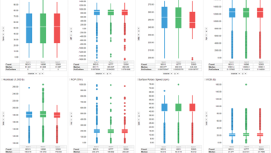
Additionally, to determine if the material meets design specifications or industry standards and specifications, mechanical tests (hardness, tensile and charpy impact tests) and chemical analyses (optical emission spectroscopy) are performed on representative samples. Energy dispersive X-ray spectroscopy (EDS) analysis is used to determine the elemental composition of corrosion deposits in conjunction with powder X-ray diffraction analysis, which identifies the crystalline compounds in a deposit.
Case I: A proprietary grade (XD 105) drill pipe parted at a length of 6 ft, 9.5 in. away from the box end. No apparent secondary cracks were evident adjacent to the fracture from wet fluorescent magnetic particle testing. Visual examination of the drill pipe revealed necking, a reduction in diameter and wall thickness, adjacent to the fracture, which was quantified by outside diameter measurements of 4.60 in. at the fracture and 4.95 in. away from the fracture. Fractography revealed 45° shear lips without any unique or identifiable fracture origins. The combination of necking and 45° shear lips indicates that the drill pipe fractured from a ductile, tensile overload.

The drill pipe had an average hardness of Rockwell C 25, with a tempered martensite microstructure, typical of steels in the quenched and tempered condition. The yield strength of the drill pipe, 122.5 ksi, was greater than the specified maximum yield requirement of 120 ksi, indicating that the length of the drill pipe had yielded, causing work hardening during the overload fracture. No apparent manufacturing anomaly was evident in this analysis, thus the overload fracture is likely attributed to operating conditions versus design.
Case II: Three parted sections from two joints of drill pipe had mechanically damaged fracture surfaces that displayed no relevant fracture features indicating their fracture modes. Wet fluorescent magnetic particle examination of the drill pipe sections revealed several circumferential crack-like indications (Figure 1). These circumferential cracks were at the base of pits with depths ranging from 0.021 to 0.060
in. One of the representative cracks was opened to evaluate the crack surface, which displayed ratchet and beach marks along with black and reddish brown deposits. Ratchet marks are observed when two or more fatigue crack origins produce cracks that join together to form a single crack front. The beach marks present on the crack surfaces indicate incremental crack growth, typical of fatigue and cyclic loading.
Based on the location of the ratchet marks and the orientation of beach marks, it was evident that the opened crack initiated at the outside surface and propagated inward. The crack surface deposits (EDS analysis) contained the elements barium, calcium and sulfur, typical of drilling muds, in addition to elements typically present in steels. Metallographic examination of a cross-section through the cracks revealed multiple transgranular cracks at the base of pits (Figure 1d).
The mechanical properties of the drill pipes were satisfactory to the requirements of specification API 5DP, grade S. Pitting corrosion (environment) produced stress risers from which fatigue cracks grew. Although no undamaged fractures were available for examination, enough secondary information was available to determine the cause of failure was fatigue.

Case III: A drill pipe contained a perforation and washout approximately 2 ft away from the face of the box end tool joint. Examination of the inside surface of the pipe revealed damage to the internal coating, likely from tools. The majority of the fracture surface was damaged by washout. However, a small inside surface crack, undamaged from the washout, was found to be caused by fatigue. The pipe had a tempered martensite microstructure, and the mechanical and chemical properties of the pipe were satisfactory for specification API 5DP grade X-95. No apparent manufacturing anomalies were evident from this analysis, and the washout is attributed to a fatigue crack that initiated on the internal surface at a corrosion pit caused by the compromised internal coating. Root cause analysis may further identify the cause of coating damage, require coating inspections and the actions required to prevent future coating damage.

Case IV: A joint of drill pipe separated circumferentially in the tool joint 1 ½ in. from a weld. Severe necking at the separation point indicated a very ductile failure. Circumferential scoring and dark colored oxides associated with high-temperature oxidation were observed on the outside surface near the failure. Examination of the microstructure near the separation of the assembly revealed untempered martensite, indicating that the tool joint was exposed to extremely high temperatures and rapid cooling at the point of failure. Friction between the upper shoulder of the tool joint and the wellbore likely generated the high-temperature exposure associated with the observed microstructural changes. The Vickers hardness of the untempered martensitic region was approximately 450 HV (HRC 45.2), whereas the tempered martensite region (away from fracture) had an average hardness of 300 HV (HRC 29.7). The chemical and mechanical properties of the representative tool joint were satisfactory. This failure is likely attributed to operational versus design conditions, and a root cause analysis would help to identify the operating parameters that contributed to the overheating of the tool joint.

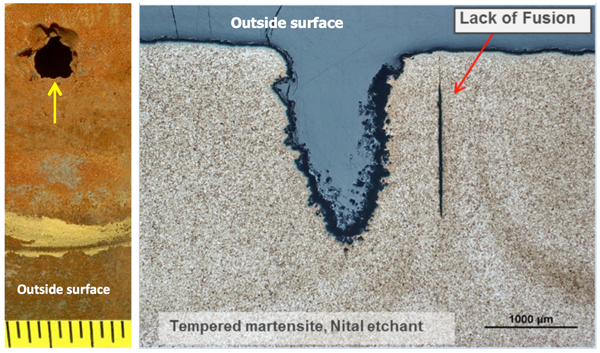
Case V: A casing joint developed a perforation. Metallographic examination of a cross section through the perforation revealed a lack of fusion weld defect in the electric resistance weld (ERW) in the joint that resulted in a leak near the middle of the joint. The lack of fusion defect was short in length and only observed at the margins of the leak. The leak occurred when the weld defect propagated through-wall, resulting in a washout from high-velocity flow eroding the sides of the lack of fusion to produce the observed round hole with fluted sides. The casing joint met the mechanical and chemical property requirements of API 5CT, Grade P110 material. The perforation of the casing is attributed to a manufacturing defect, which can be further investigated by root cause analysis.
Case VI: A section of 4 ½ in., P110 casing suffered a longitudinal rupture along the ERW weld seam as a result of a lack of heat treatment to the weld seam and pipe. The ERW weld and base metal had a hardness of Rockwell C (HRC) 55 and a Rockwell B (HRB) 94, respectively.
Untempered martensite was observed in the high hardness weld, while a ferrite-pearlite microstructure was observed in the low hardness base metal. Grade P110 material requires a quenched and tempered microstructure with minimum tensile strength of 125 ksi (a minimum hardness of approximately 26 HRC). This indicates that the pipe was not heat-treated after welding. To obtain a hardness of 26 HRC, a quenched and tempered microstructure is required, which was not present in the base metal. So, not only was the weld not stress-relieved, the pipe wasn’t provided in a quenched and tempered condition. The lack of heat treatment resulted in a brittle ERW weld and low strength in the pipe body, thereby causing the observed fracture and separation. The casing did not meet the requirements of API 5CT grade P110. Root cause analysis can investigate the manufacturing and quality control issues that allowed for the production of a non-conforming casing joint.
Case VII: API 5CT grade P110 requires joints to be provided in a quenched and tempered condition, i.e., have a tempered martensite microstructure. However, during a routine receiving inspection, it was determined that four out of seven joints from multiple heat lots had improper heat treatment, thereby resulting in a ferrite-pearlite structure. The ferrite-pearlite microstructure is typical of steels in the normalized condition. A lack of proper heat treatment results in lower mechanical properties, thereby leading to premature in-service failures.
From these case studies, it is apparent that failure analyses provide the critical input required for performing a thorough root cause analysis, as illustrated by Figure 2. DC
This article is based on a presentation at the 2017 IADC Asset Integrity & Reliability Conference, 22-23 August, Houston.