Longer, deviated wells push drill pipe limits
Without further advances, pipe could become limiting factor in tomorrow’s drilling programs
By Thomas M. Redlinger and John McCormick, Weatherford International
Drill pipe technical performance is rarely the starting point for well planning – engineers expect that drill pipe will handle the challenges, loads and environments that it encounters. Until recently, drill pipe has been able to keep ahead of drilling challenges. “Dumb iron,” as it is described in the industry, has evolved into a highly engineered drilling product, designed with features to reduce drilling fatigue, improve torsional and tensile strength, resolve slip crushing issues, and allow it to operate in sour drilling conditions.
Now, however, drill pipe features no longer far exceed the expectations of drilling programs. Without further improvements to materials, connections and fatigue life, the capabilities of the drill pipe could become the limiting factor in state-of-the-art drilling projects on the horizon.
Drilling History
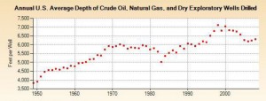
Drilling operations today are considerably more complicated than they were 50 years ago. One significant change relates to the depth wells now regularly achieve. In 1950, the average depth of exploratory wells in the US was less than 4,700 ft. By 1990, the average depth was around 6,000 ft, and by 2000 the average well depth in the US reached a peak of nearly 7,000 ft. Furthermore, these wells are increasingly complex directional or horizontal wells.
Although the concept of drilling a horizontal well was developed as early as 1891, with Smalley Campbell’s patent on using a flexible shaft to rotate drill pipe, the first recorded truly horizontal well was not completed until 38 years later in Texas, and the regular practice of drilling horizontal and directional wells was not achieved until the early 1980s.
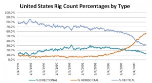
Horizontal drilling is commonplace. In the 1990s, less than 10% of the wells drilled were horizontal. Horizontal wells now account for more than half of all drilling activity in the US. At the same time, the complexity and difficulty of these wells is also being pushed, further challenging the limits of the drill stem.
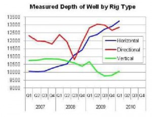
The measured depth and departure of a horizontal well are often used as the variables to indicate total drilling complexity. From 2007 to 2010, the average measured depth of horizontal wells in the US increased from 10,000 ft to over 13,000 ft. The increase in horizontal departure is even more significant over a longer period of time.
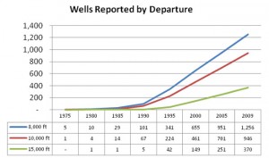
A review of extended-reach drilling (ERD) from 1975 shows the extended-reach drilling record had a maximum departure-to-depth ratio of 2:1, barely achieving today’s definition of an extended-reach well. Today, the common definition of an extended-reach well is a well profile that has a step-out ratio above 2:1, although it has been suggested that the definition of extended-reach should focus on the departure relative to the equipment, total vertical depth and water depth.
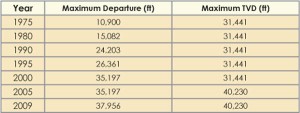
The maximum ERD departure in 1975 was an absolute departure value of 10,900 ft (Table 1). The industry began regularly drilling these types of wells in the late 1980s and early 1990s. Today, the departure record is nearly four times the 1975 record, at 40,230 ft drilled by Maersk Oil. The departure-to-depth ratio is now over 10-to-1. Many technologies and products have been credited for the success of these drilling operations, including high-strength and high-torque drill pipe.
However, the industry’s ability to continue advancing the drilling of these extremely challenging wells has slowed in recent years. From 1975 to the mid-2000s, ERD record-holders frequently changed. In the last five years, however, there has been only a slight change in the departure record and no change in the maximum total vertical depth (TVD), as Table 1 indicates. Complex wells continue to be planned, but the equivalent circulating density (ECD) effects and torque and tensile limitations of the drill pipe often result in well designs that need to be modified to operate safely within the drill pipe ratings.
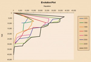
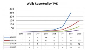
Dividing the standard industry drilling envelope by year, it can be seen how ERD may have begun to reach their technical limits (Figure 1). Each successive drilling record is taking much smaller steps from the previous record.
Although record-breaking wells are in a category of their own, today’s drillers regularly break the drilling records of the 1980s without significant planning. The early 1980 definition of a “superdeep well” was drilling below 15,000 ft. Most of these 15,000-ft wells were vertical or near vertical in design. Today, wells with 15,000 ft measured depth are not uncommon.
Data from Spears show the 2010 average measured depth for directional and horizontal wells drilled in the US was over 13,000 ft. Although this data is not a complete record of the wells drilled, it does demonstrate a trend in the industry to continually surpass the 15,000-ft measured depth mark. By the end of 2005, more than half of the wells reported to the industry drilling envelope were deeper than the “superdeep” 1980s mark. This is a credit to the reliability of technologies used to reduce risks in these operations. The drillstring is among the components that can be regularly depended on to withstand the load at these depths.
Further, the first extended-reach wells took over a year to complete. Today, a 20,000-ft ERD well can be completed in less than 60 days.
As drilling challenges continue to evolve, new projects are now expected to achieve measured depths in excess of 50,000 ft. Among the technical limitations will be the capability to handle the torque required to drill on bottom and the tensile requirements to complete the casing plans. Both of these limitations involve further advancements in drill pipe technology.
Drill Pipe History
Drill pipe is rarely considered to be a high-technology product; most of the industry refer to it as “dumb iron.” Drill pipe has, however, evolved significantly over the last 60 years. What was originally a simply threaded and coupled tubing product now has a highly engineered and controlled design.
To better understand how drill pipe has evolved from couplings and tubing to its current design, it is important to follow the design milestones.
The most significant drill pipe milestone occurred in the late 1950s, when the threaded and coupled design was eliminated in favor of the friction-welded design. The friction-welded design replaced the threaded tooljoint with the welded tooljoint, removing a significant stress riser at the connection. This design also allowed for new and more durable connection designs. The original connection designs were supplied by many manufacturers, and they were not all compatible. In the early 1960s, API standardized the connection and added additional fatigue design elements.
These two simple innovations reduced the fatigue failures and removed the drill pipe from being the critical restriction on potential drilling depths and well profiles.
Shortly after introducing these innovations, the average drilling depths in the US dramatically changed – going from 4,000 ft in 1950 to 6,000 ft in 1970.
For the next decade, there was little substantial change in drill pipe design to improve its performance or capabilities. The next major milestone was the evaluation and design improvements related to washouts near the internal upset in the drill pipe tube. Many studies were conducted and industry papers written to establish the root cause and develop corrective design features.
Drill pipe with MIUs shorter than 1 in. (25.4 mm) were found to often fail in less than 500 rotating hrs. In the mid-1980s, the API standard for drill pipe, API 5AX, did not attempt to control the minimum length of the internal upset, which resulted in the emergence of a variety of profiles, depending on the manufacturer. API now specifies a minimum MIU of 2 in., although today’s premium drill pipe can have MIUs that are over 4 in. in length.
This improvement, combined with internal plastic coating, has noticeably reduced the number of washouts in drill pipe. Although washouts rarely affect the ability to reach the drilling target, they create expensive difficulties during deepwater operations.
Sour-service
The metallurgy of “high-strength” drill pipe has continued to improve over the last few decades. This includes vendors’ ability to tightly control the manufacturing process in order to predictably control the mechanical properties of the final product. Normalized grade “E-75” drill pipe and quenched and tempered “X-95” and “G-105” were the only choices for sour-service drilling until the early 1990s.
These grades of drill pipe, although acceptable for some sour-service drilling, were not ideal. Drilling with these grades of pipe in moderate or highly sour well environments often led to drillstring failures. The E, X and G grades also reduced industry’s drilling potential by limiting the maximum tensile strength of the pipe.
Today’s H2S-resistant drill pipe can be used in almost all harsh sour drilling environments and include a variety of configurations to meet the level of sour resistance needed. Every section of the drill pipe can now be manufactured to some level of sour service. The tooljoints, tube body and even the friction weld at the upset can be controlled for some sour-service resistance.
Design work in this area continues to increase the drill pipe’s resistance to sour environments, and manufacturers expect that they will be able to begin to commercialize new sour-service drill pipe in the coming years that has a minimum yield above 120 ksi. New standards for sour-service pipe are being developed by NACE and the IRP drill pipe committee, which will require tighter controls of the metallurgy.
Connections
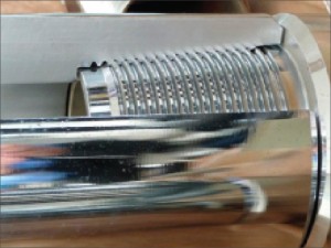
Tooljoint connection technology remained largely unchanged from when API modified the connections to the NC connection in the early 1960s until the early 1990s. After decades of the average drilling depths staying nearly the same, operators began to push the torsional limitations of the drill pipe connection. The industry quickly responded with a second generation of drill pipe connections. The new connections used the same taper and thread profile as the standard API “NC” connection but added a secondary internal shoulder (Figure 2), which increased the torsional capabilities of the drill pipe by over 40%.
The secondary effect of adding the internal shoulder was the ability to make the connection more hydraulically streamlined. By reducing the OD and increasing the ID of these connections, operators were able to use larger tube sizes of drill pipe, increasing tensile capacity in smaller holes.
Additionally, the new connections reduced the overall hydraulic loss per foot of the drillstring. On rigs where hydraulic or ECD issues limited the casing or drilling program, these improvements opened a new range of drilling possibilities. Our drilling programs regularly include this type of drill pipe to advance the drilling of horizontal wells, and this technology was included in many of the deep and extended-reach wells of the 1990s.
The next series of drill pipe connections offered an even slimmer profile, improving fatigue resistance, and further pushed torque and tensile capacities. These connections abandoned the API or NC taper and thread profiles for their own specific designs. Proprietary double-shouldered connections (DSCs) are now widely used in applications where the API drill pipe from the 1980s would not have been fishable or would have generated too much hydraulic pressure loss to complete the drilling program.
Table 2 shows the evolution and impact of the connection technology on 4-in. and 5 ½-in. drill pipe. The standard NC38 connection using today’s OD and ID requirements would have only a makeup torque rating of 12,000 ft-lbs. The torsional ratio of connection to tube at 0.48 would be well under the generally accepted guideline for connection design and would likely not be a recommended configuration. The NC40 connection would be a suitable alternative but requires a larger tooljoint OD. This change in tooljoint OD complicates any potential fishing operation in 6 ¼-in. hole and increases the hydraulic losses to almost 1,700 psi per 1,000 ft.
By switching to the API double-shouldered connection, the hydraulic performance, torsional properties and OD are all improved. This can be further improved by advancing to the proprietary versions of the drill pipe connections. These connections further “slim” the connection profile and improve performance metrics by 10% more. Today’s advances in connection technology are focused on reducing the time required to make up the connection and enhancing fatigue resistance. Even with the planned improvements, most downhole equipment designers strive to develop tools as strong as and with similar fatigue resis tance as the drill pipe they are carried in. Drill pipe performance metrics are used to determine whether the bottomhole assembly tools are oilfield ready.
Other enhancements
Drill pipe has evolved to continually stay ahead of industry’s drilling requirements, and manufacturers continue to add design features into what many consider to be a simple product. They have developed innovative methods to include a “slip proof” section to eliminate slip crushing while under significant loads in excess of 2 million lbs. Current landing string technology allows for the manufacture of 6 5/8-in. drill pipe with wall thickness nearing 1 in. and minimum yield strength above 165 ksi.
New developments in thin-walled drill pipe significantly improve the strength-to-weight ratio of drill pipe. The addition of telemetry is also possible with “wired” drill pipe, which is poised to change the way the industry evaluates formations.
With all of these innovations from the past and more innovations on the near horizon, it is hard to think of drill pipe as “dumb iron.”
Analytical review
As discussed, ultra-deep wells (UDWs) and extended-reach wells (ERWs) are becoming more and more commonplace. Not only are they drilled with greater frequency, but they are also increasing in reach and depth. Drill pipe has historically been stronger than the forces and stresses placed on them – by far. With the increasing depth of UDWs and reach of ERWs, the technology and operating limits of pipe are being reached. Drilling practices in various areas around the world, such as gas shale plays in the US, are also challenging drill pipe limits.
This section will present examples of wells that have reached or exceeded the limits of today’s drill pipe, even with the proprietary DSCs, S-135 grade and advanced metallurgical and manufacturing processes. An example of torque limitation, tensile limitation, landing string stress and loading limits, and an ultra-ERW are presented. In each of these cases, the limitations of the pipe and the solutions sought will be discussed.
Torque Limitations
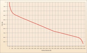
An example well in the continental US is representative of the highly deviated build-and-hold wells that are quite commonplace in the industry today. The deviation of the well approached 78° from vertical (Figure 3). It is interesting to note that this well, as with many other wells that were drilled in 2010, experienced high torque despite not qualifying for the term extended-reach.
The string of 5 7/8-in. pipe with XT 57 connections has a makeup torque of 57,000 ft-lbs. Torque-and-drag modeling prior to drilling showed the torque at TD to approach or exceed the makeup torque of this API DSC design (Figure 4). In this case, mechanical friction-reduction tools were eventually used to decrease the torque enough to drill to TD.
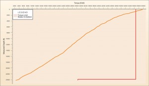
Also of interest is that the production liner run to TD employed both roller centralizers on the liner itself and mechanical friction-reduction tools on the landing string. Despite this assistance, the liner experienced enough drag that it was set a couple of hundred feet above the target depth.
Tensile Limitation
Possibly the most severe tensile situation for pipe during a common operation is experienced by drill pipe used as landing strings while running long liners. In addition to the concern of exceeding the tensile yield of the pipe, slip crushing and handling issues must also be considered. Common changes made in response to the large loads include thicker pipe walls, increased slip segment lengths and material grades stronger than S-135.
Although API requires new pipe to be built to greater than or equal to 87.5% wall thickness, service companies, operators and manufacturers commonly have established internal standards of greater than or equal to 95% wall thickness for “fit-for-purpose” landing strings. Material grades of 140 ksi and 150 ksi are available and are being used. 165-ksi steel is being aggressively researched for application in the field.
However, to handle axial loads in excess of 1.5 million lbs, more dramatic changes have become necessary. A paper presented at an SPE conference last year, “Deepwater and Critical Drilling with New Connection Technology,” discusses additional improvements made within the past few years for landing strings. The crushing loads placed on drill pipe can cause the pipe to fail in the slips prior to a tensile failure, necessitating heavy-walled slip sections. A dual OD tooljoint provides a larger area in contact with the elevator, which increases the capacity of the elevator to handle high tensile forces while also meeting the requirements for fishing.
Extended-reach wells
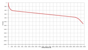
The current limitation for ERWs and UDWs is approximately 40,000 ft MD. Maersk Oil currently has the longest shallow ERW, ExxonMobil has the longest intermediate ERW, and GNPP Nedra has the longest UDW. Projects are being evaluated by multiple companies around the world that are either unobtainable or almost unobtainable. One of these projects is evaluated below.
Several companies are evaluating the possibility of drilling ERWs from onshore to reach offshore reservoirs. Alternative solutions are to use an offshore structure or build an artificial island, both of which are challenging and extremely costly.
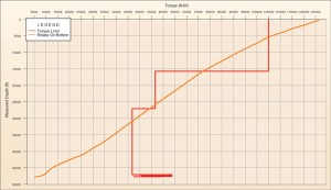
Torque is commonly a limiting factor in drilling ERWs, although drag does come into play when running long casing strings and liners. Figure 5 demonstrates the difficulty that torque can cause in an extended-reach well that pushes the envelope of what is achievable today. The string shown is composed of 6 5/8-in., 5 7/8-in. and 5 ½-in., all with high-torque connections.
Any time an ultra-extended-reach well is planned, alternative materials are considered. Aluminum is a common point of discussion, along with titanium and composite pipe. With the introduction of steel grades above the common S-135, another discussion on thin-walled pipe has begun. Using 165-ksi material, it is possible to achieve the same strength as a standard joint of S-135 pipe with a reduced wall thickness. The lower weight of a thin-walled pipe reduces the normal forces that lead to higher torque and drag. Increased flow area through the pipe is another benefit.
The challenges come with the loss of wall thickness through abrasion, fluid erosion and corrosion. Each thousandth of an inch of wall thickness lost with high-strength, thin-walled pipe is equivalent to a larger loss in a thicker S-135 equivalent.
With drilling programs reaching or approaching the technical limits of the drillstring, several industry changes have occurred over the past decade, most notably the increased focus on drill pipe inspections, which have increased in frequency and scope. Several organizations, including TH Hill and Fearnley Proctor, have developed industry-accepted standards for the inspection of drill pipe. These standards are widely used to ensure the pipe will meet the high demands of newer drilling programs.
API recently completely revised its recommended practice for drill pipe inspection in API RP 7G-2, including several categories of inspection. Along with the addition of these new inspection standards, a new third-party inspection “audit” service industry has been created.
The frequency of “critical” drill pipe inspections and “audits” of these inspections is on the rise. Many of the critical drillstrings are required to have a minimum 95% remaining body wall to be sufficient to meet operational demands. These drillstrings already include improved material grade technology and improvements to wall thickness but are allowed less than a 5% reduction in wall prior to being deemed “not fit for purpose.”
It is clear that advances in these critical drillstrings are needed. As industry attempts to move forward and further its drilling programs, collaboration between operators, well planners, drill pipe manufacturers and service companies must be expanded.
Conclusion
Over the last 50 years, drill pipe tensile and torsional capacities have typically exceeded industry’s needs in most drilling applications. Drilling has continued to trend toward drilling deeper, longer-reach wells. Although improvements in drill pipe, performance and connection technology have significantly advanced, industry’s drilling programs have begun to push the limits of drill pipe capacities. Without further improvements to materials, connections and fatigue life, the drill pipe could become the limiting factor in exciting new projects on the horizon.
It is essential that suppliers, including rental companies, and manufacturers, play a larger role in well planning to mitigate these limitations and make sure the technologies required are available to the industry in time to coincide with the new drilling projects.
This article is based on IADC/SPE 139410, “A Historical Review of Drill Pipe Capabilities and the Triggers for Change,” presented at the IADC/SPE Drilling Conference & Exhibition, 1-3 March, Amsterdam, The Netherlands.
References
- Jellison, M.J., Spoerker, H.F.: “Advancements for Critical Drilling Applications” SPE 118737, presented at the 2009 SPE Middle East Oil & Gas Show, Kingdom of Bahrain, 15-18 March 2009.
- Jellison, M.J., Spoerker, H.F., Chandler, R.B: “Advanced Technologies and Practical Guidelines for Challenging Drilling Applications” SPE 135148, presented at the 2010 SPE Russia Oil & Gas Show, Moscow, 26-28 October 2010.
- Jellison, M.J., Chandler, R.B: “Deepwater and Critical Drilling with New connection Technolgy” SPE 13857, presented at the 2010 SPE Asia Pacific Oil & Gas Show, Brisbane, Austrialia, 18-20 October 2010.
- Energy Information Administration, “Drilling Sideways – A Review of Horizontal Well Technology and Its Domestic Application” DOE/EIA- TR-0565, April 1993.
- Chandler, R.B, Jellison, M.J., Skogsberg, J.W., Moore, T.: “Advenced Drill String Metalurgy Provides Enabling Technology for Critical Sour Drilling” NACE paper 02056, 2002.
- Jellison, M.J., Chandler, R.B, Sheppard, J..: “Challenging Drilling Applications Demand New Technologies” IPTC 11267, presented at the 2007 International Petroleum Conference, Dubai, U.A.E., 4-6 December 2007.
- Brock, J.N., Jellison, M.J., Chandler, R.B, Sanclemente, L.W., Robichaux, R.J., Saleh, M.: “2 Million – lmb Slip-Based Landing String System Pushes the Limit of Deepwater Casing Running” OTC 18496, presented at the Offshore Technology Conference, Houston, USA,30 April – 3 May 2007.
- Chandler, R.B, Jellison, M.J., Payne, M.L., Shepard, J.S.: “Performance Driven Tubular Technologies” SPE/ IADC 79872, presented at the 2003 SPE/IADC Drilling Conference, Amsterdam, The Netherlands, 19-21 February 2003.
- Wilson, G.E., Shepard, J.S., “What difference does MIU make in fatigue life of Drill Pipe” IADC/ SPE 23841, presented at the 1992 IADC/ SPE Drilling Conference, New Oreleans, Louisiana, USA, February 18-21, 2003.




i do have one one inovation on pre existed tool jonit ….named it as flexible lock and unlock tool joint….can provide flexibility and rigidity at the same time while drilling a curve section of short radius horizontal well….it allows the drill pipe to take the shape of the curve section…im from india …colge pdpu
I read about 1 yr ago the Saudis drilled a 20,000 depth well about 10 miles west of Houston Tx and found natiral gas ….could you please verify this?…..Also the name of the Russian contact who develpoed the drilling technology….Thank you ..also has any one drilling to the 50,000 ft depht that you stated in your article?
Shand Group products PVC pipes, Plastic Pipe, pipes & fittings, PVC pipes & fittings, Column pipes, CPVC Pipes & Fittings manufacturers, Exporters, Suppliers in bangalore India . Shand Group conform to highest levels in quality and are tested for strength and durability under the most stringent international standards.
Column pipe manufacturer
Plastic Pipe Exporters
Manufacturer of pipes & fittings
CPVC Pipes & Fittings manufacturer
PVC pipes & fittings manufacturer
For more details visit :- http://www.shandgroup.com/
Can you supply drilling pipes for contract