Study simulates kick responses during MPD
Experimental wells confirm alternative well control procedures to be effective in range of well conditions
By J.E. Chirinos, J.R. Smith, D.A. Bourgoyne, Louisiana State University
According to IADC, managed pressure drilling (MPD) is defined as “an adaptive drilling process used to precisely control the annular pressure profile throughout the wellbore.” The technology uses different approaches to control and influence wellbore pressure. It is able to actively manipulate the wellbore pressure profile by controlling backpressure, drilling fluid proprieties and circulating friction; hence, a combination of tools is used to achieve MPD objectives to reduce nonproductive time (NPT) and mitigate drilling hazards.
MPD has been shown to be successful in wells where kicks, lost returns, ballooning, wellbore instability and/or differential sticking cause excessive NPT or inability to reach objectives using conventional drilling methods.
Although the main application of MPD has primarily been drilling in a narrow margin between pore pressure and fracture pressure, it’s increasingly realized that MPD can be applied anywhere where more precise control of wellbore pressure is an advantage. As a result, the industry has addressed a significant number of challenges by using MPD. Applications include: narrow drilling margin between pore pressure and fracture pressure, depleted formations, tight-gas sands, shallow gas hazards, wellbore stability problems, fractured carbonates, HPHT wells, H2S wells, slim-hole coiled-tubing drilling and casing drilling.
This article focuses on one variation of MPD – constant bottomhole pressure (CBHP) – which uses a combination of equipment to manipulate annular frictional pressure losses and casing pressure to keep wellbore pressure at a selected depth relatively constant. Although the CBHP method of MPD has better control of wellbore pressure while drilling, well control events can still occur because of uncertainty related to pore pressure and fracture pressure, human error or equipment failure.

Several alternative well control procedures during the application of the CBHP method have been studied by industry-supported research to establish a basis for determining appropriate procedures. This research has defined two non-circulating responses as preferable among multiple alternative non-circulating responses. These two responses are described as a simple shut-in and as a MPD pump shutdown with a “choked flow check.” Both require a pump startup schedule to begin circulating out a kick. The goal of this article is to explain and document these procedures and to demonstrate by applying them in computer simulations and to gas kicks taken in a full-scale experimental well.
CBHP Method of MPD
The CBHP method is the most common variation of MPD. During its application, annular pressure in the well is held constant or near constant at a selected depth. CBHP actively controls the surface pressure using a drilling choke to compensate for changes in frictional pressure losses (ΔPAF) during routine operations, such as making a connection.
An important characteristic of this method of MPD is the minimization of wellbore pressure variation to keep wellbore pressure within the drilling margin. Consequently, it allows drilling within a narrower window, or margin, between fracture and pore pressures than conventional drilling methods.
CBHP uses a collection of tools to control wellbore pressure during drilling operation. The minimum equipment required to apply CBHP are a rotating control device (RCD), a drilling choke manifold and, typically, a non-return valve. The RCD keeps annular space closed and diverts flow to the drilling choke; it is equipped with a rotating packer that rotates and holds pressure in the well during drilling operations.
The drilling choke manifold helps manipulate and control surface pressure while drilling; it can be controlled manually, semi-automatically or automatically. A non-return valve or float valve is installed in the bottomhole assembly; it allows only downward flow of drilling fluids, which is necessary if the well will be statically underbalanced.
Other optional tools can complement CBHP operation to improve wellbore pressure management, such as coriolis meters (flow meter), continuous circulating systems, downhole deployment valves, backpressure pumps, surface multiphase separators, pressure-while-drilling tools (PWD) and hydraulic flow modeling.
Pump Shutdown, Pump Startup Schedule
Many authors have discussed the method used to transition from dynamic to static state during CBHP. Medley, et al, and Rehm, et al, described a method to achieve CBHP objectives when rig pumps are shut down. It relies on a hydraulic model to estimate annular friction losses and equivalent circulating density (ECD) at different pump rates. Then, the ECD is manipulated by adjusting the casing pressure to keep wellbore pressure constant when the pump rate is reduced.
Wellbore pressure and ECD estimates are made with hydraulic models and can be validated with PWD tools. For example, to make a connection, the choke opening is reduced to increase casing pressure to the desired pressure, then the pump rate is reduced. Thus, surface pressure increases as the frictional pressure loss decreases by an equal amount. This process continues stepwise until the annulus surface pressure is at the maximum calculated value and the pumps are stopped.
The final annulus surface pressure should be equal to the frictional annulus pressure losses in the well, plus any surface backpressure held during normal operations.
Initial Responses during Well Control Operation
A few studies have been done in the area of initial responses to well control events for the CBHP method of MPD. Das (2007) documented the first research from the university-industry consortium related to initial responses to a kick taken during the CBHP method. He compared three initial responses by using computer simulation: shutting in the well conventionally, increasing choke pressure while keeping the same pump rate, and increasing pump rate while keeping choke pressure constant. The most important conclusions from this research were: a) no single response was identified as the best, b) circulating responses may stop the influx faster than non-circulating responses, and c) the increased choke pressure response leads to a lower shoe pressure than shut-in, thus it reduces the risk of lost returns at the shoe.
In 2009, Guner studied the most appropriate initial response and kick circulation method for an unexpected reduction of bottomhole pressure created by a surface equipment failure or unintended ECD reduction. The conclusions explained that shut-in was the initial response that is applicable for all kick scenarios; however, increasing choke pressure would generally be the most effective response when it was practical. For both responses, Guner recommended kick circulation at the normal drilling circulation rate.
In 2009, Davoudi documented a comprehensive investigation of alternative initial responses to gas kicks taken during drilling operations with the CBHP method. He studied nine responses, five of them non-circulating and four circulating responses. They were compared based on the ability to stop formation flow, minimizing the risk of lost returns and additional kick influx, and the reduction of pressure imposed at surface and the casing shoe.
Davoudi performed more than 150 simulations and found that no single best initial response to all kicks could be identified. However, three initial responses were demonstrated to have a broad application to different kick scenarios: a rapid increase of casing pressure until flow out equals flow in, a simple shut-in, and an adaptation of the MPD pump shutdown schedule that allowed confirmation of low rate kicks using a choked flow check. In addition, he concluded that the best initial response depended on well conditions and the equipment being used.
Based on the consortium research, Davoudi, et al (2010) presented a proposed approach for selecting initial responses during well control events for the CBHP method. They explained that one criteria in selecting the initial kick reaction must be the equipment available onsite, specifically whether flow-out metering was being used.
In addition, according to this approach, the selection of the initial response should consider the certainty of the well control event. Each initial response has key factors that need be considered to ensure applicability and efficiency during the well control operations.
Research Method
This article focuses on evaluating proposed procedures for the two non-circulating kick responses described by Davoudi in 2010 and on the pump startup procedure for kick circulation after a non-circulating response is applied. Two approaches were used to evaluate and confirm the applicability of these procedures: computer simulations and full-scale experiments.
Non-Circulating Responses
Simple Shut in
This response is widely known and accepted in conventional operations. However, according to work by Gunner in 2009, the simple shut-in procedure can be applied in MPD operation where accurate flow metering is not available or where equipment failure endangers the operation. This procedure can be summarized as:
1. Stop drilling, i.e., pick up off bottom and stop rotating.
2. Shut down the pumps as quickly as practical.
3. Close the drilling choke as quickly as practical.
4. Record shut-in casing pressure (SICP) versus time.
MPD Pump Shutdown with Choked Flow Check and Shut-in
This method is based on the pump shutdown schedule for routine operations in CBHP. It can be used to check for flow when signals of a kick are not clear. The procedure can be outlined as:
1. Stop drilling, i.e., pick up off bottom and stop rotating.
2. Apply the regular pump shutdown schedule.
3. At the end of the schedule, attempt to hold the casing pressure constant for approximately two minutes by adjusting the drilling choke.
4. If it is necessary to bleed fluid from the well to maintain a constant casing pressure, shut in the well by closing the drilling choke and record SICP versus time.
5. If not (i.e., if the casing pressure does not increase above the final schedule pressure with the choke closed), resume drilling operations but continue monitoring for kick warning signs.
The application of these non-circulating responses is dependent on the RCD static pressure rating. If the expected shut-in casing pressure will exceed the RCD rating, close the annular preventer or pipe rams and open the choke line valve with the well control choke closed rather than closing the drilling choke.
Pump Startup Schedule after a Non-circulating Response to a Kick
Pump startup and pump shutdown procedures are routine MPD operations that are intended to keep wellbore pressure relatively constant during pump manipulations. When a non-circulating response is applied, a new pump startup schedule to start kick circulation is needed. This procedure should keep BHP relatively constant and above formation pressure.
The goal of this part of the research was to document and evaluate a simple method to start the kick circulation and keep bottomhole pressure constant after a non-circulating response. The method uses information available on the rig to define a pump startup schedule.
The proposed procedure is:
1. A routine pump startup schedule should already exist. Table 1 shows an example of a pump startup schedule with four steps of increasing pump rate, Q1 to Q4. As can be seen from the table, when the mud pumps are off, the casing pressure (CP) is equal to the annular friction pressure loss (ΔPAF) plus a desired casing pressure for routine operations (CP*). Notice that during the startup, CP is reduced by a constant pressure increment (ΔP) at each step until it is equal to the CP*.
This schedule keeps BHP approximately constant while the mud pump rate is increased. Note that a pump shutdown would use this same schedule beginning at Q4 and reducing the pump rate.
2. Once a potential kick has been recognized and the relevant non-circulating response applied, is recorded until a stabilized SICP can be interpreted.
3. Based on the stabilized SICP and the routine pump startup ΔP defined in step 1, a post-kick pump startup schedule is defined for the MPD kick circulation. Table 2 illustrates a post-kick pump startup schedule equivalent to the routine schedule in Table 1. CP0 is selected as equal to SICP plus a desired safety overbalance factor (ΔPOB). At each step in the schedule, the CP is reduced by the same ΔP, and the flow rate is increased to the same Q as defined for the routine pump startup.
4. Once the post kick pump startup schedule has been applied, the pump rate stabilized at Q4 and the choke pressure stabilized at CP0 Kick – 4ΔP, the drill pipe pressure should also stabilize. The kick is then circulated out, keeping drill pipe pressure constant at that value and the pump rate constant at Q4, equivalent to the driller’s method of well control.

Well Scenarios for Evaluating Procedures
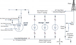
LSU #2 is a 5,884-ft deep vertical well with 9 5/8-in. casing. Most of the full-scale results of this research were measured in and then compared with computer simulations of LSU #2. Two additional well geometries were used to perform simulations representative of other drilling environments suitable for MPD application: Well X is a 6-in. slim-hole directional well with a potential deep kick zone whereas Well Y is 12 ¼-in. straight hole with a potential high-pressure sand at the bottom.
Simulation Procedure
The computer simulations start during drilling operations just above the high-pressure sands in wells X and Y. For LSU well #2, a high-pressure sand was created in the simulator to emulate real conditions. The bit would drill into the high pressures, where a gas kick would be taken. Two initial responses were used to stop formation flow: simple shut-in and manual MPD pump shutdown with a choked flow check. If a simple shut-in response was used, the pumps were shut down, and then the choke was closed as fast as practical. However, if a manual MPD pump shutdown with choked flow check was performed, the pump shutdown schedule for routine operations was applied.
At the end of the schedule, the casing pressure that was required to compensate for the lost annular friction (ΔPAF) was held constant for approximately two minutes before shutting the well in, unless shutting in was required to maintain casing pressure. In both cases, SICP was recorded and used to create a pump startup schedule for kick circulation. All simulations were carried out until the gas was circulated completely out of the system; the data was recorded and analyzed using a spreadsheet.
Experimental Procedure
In the experimental well LSU #2, drilling fluid was circulated down the annulus between the 3 ½-in. and 1 ¼-in. tubing at the desired pump rate, and the flow returns were taken through 3 ½-in. by 9 5/8-in. annulus. The gas kick was emulated by injecting gas in the 1 ¼-in. tubing until the desired pit gain was obtained. Subsequently, the planned initial response was applied to stop formation flow and circulate out the kick. The influx was circulated out through a mud-gas separator, where the gas was directed to the flare and the drilling fluid was returned to the mud pits.
During the experiments, the drill pipe, casing and gas-injection pressures at the surface were continuously monitored and recorded, and subsequently analyzed.
Full-Scale Experiment
Pump Startup, Shutdown for Routine Operations
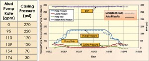
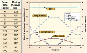
The method described was tested in a full-scale experiment in the LSU #2 well. The drilling fluid used in the experiment was water, and the kick fluid was natural gas. A restricted valve was used in a surface return line to simulate higher annulus frictional pressure losses. Conventional detection for kicks was used in this experiment. The pump startup and pump shutdown schedule for normal conditions is detailed in Table 3, and Figure 2 shows its application. Solid lines represent data from the actual well, and dashed lines correspond with data for the equivalent computer simulation. Notice that BHP was kept essentially constant during pump startup and pump shutdown.
Simple Shut-in and Pump Startup after the Kick
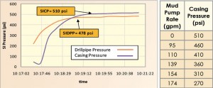
The full-scale experiment was performed according to the procedure explained above. Gas was injected into the well until a 10-bbl kick was recognized. Then the well was shut in, and SICP was recorded vs time. The initial circulating underbalance was approximately 240 psi. Figure 3 shows shut-in drill pipe (a non-return valve was not used) and casing pressure buildup; the stabilized SICP was interpreted to be 510 psi.
Table 4 illustrates the post-kick pump startup schedule based on the pump startup for normal conditions in Table 3 and the SICP. In this experiment, ΔPOB was assumed to be equal to zero.
Once the post-kick pump startup schedule was prepared, it was applied manually by two persons: one operated the pump and the other manipulated the choke to control casing pressure. Figure 4 shows the experimental results.
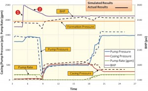
It can be observed from the graph that BHP was kept almost constant during the post-kick pump startup, which achieves the goal described in previous section. Notice that the drill pipe and bottomhole pressure results from the experiment (solid lines) and the simulation (dash lines) are not identical for this case, probably because it was difficult to get exactly the same casing pressure versus time in the simulation as in reality.
However, the similarity in behavior supports the relevance of using simulations for this study. In the plot, number 1 represents the moment when the valve from the gas source (a well that is essentially a gas storage bottle) was opened to the LSU #2 well; notice that BHP increased more than 500 psi. Number 2 in the plot shows how the pressure in the gas-storage well is reduced as the gas is injected into the LSU #2 well to simulate the gas kick. BHP was controlled when the shut-in procedure was applied.
MPD Pump ShutDown with Choked Flow Check, Shut-in
The second non-circulating response was applied to a low feed-in rate kick. The gas-storage well pressure was set to cause a 100-psi underbalance in LSU #2. A restricted flow path from the storage well was opened, a slight increase in return flow was detected as an indication of a possible kick, and the manual MPD pump shutdown with choked flow check was applied.
Figure 5 shows the experimental results. It can be seen that the pump shutdown schedule described in Table 3 was applied to keep BHP constant. The choked flow check was extended over a period of about five minutes to show that the choke had to be opened periodically to maintain the intended casing pressure at the end of the MPD shutdown schedule.
When the choke was subsequently closed, the casing pressure would build back up, indicating that the well had been underbalanced. The experimental results from the test well were also compared with a computer simulation for the same conditions, shown in the dashed lines. Although the time response of casing pressure in the simulation is not an exact match to experiment, both the trends and the magnitude of the response to choke manipulation are similar.
Example Simulations of Shut-in and Pump Startup
Simulations were conducted to provide a basis for evaluating the application of pump startup schedules to a wide range of well conditions. This section describes an example of these simulations.
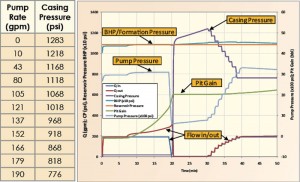
A pump startup schedule was defined to keep BHP constant during pump manipulations (Table 5) for Well X. Figure 6 shows the simulation of the pump startup and pump shutdown for routine operations for the well. It can be seen that BHP is kept almost constant while the pump is being started and shut down.
Notice that casing pressure is used to compensate the loss of friction in the well; it is increased when pump rate is reduced, and it is reduced when pump rate is increased.
Once the pump startup schedule for routine operations was defined, the kick simulation was run according to the procedure described in an earlier section. The well was drilled into a high-pressure sand with a circulating underbalance of 0.2 ppg. As a result, a 20-bbl kick was taken, the well was shut in, and SICP was recorded.
Based on the pump startup schedule for routine operations (Table 5) and the SICP, a new pump startup schedule (Table 6) for kick circulation was built, and the kick was circulated out successfully. The stabilized SICP was equal to 1,183 psi. A safety overbalance (ΔPOB) of 100 psi was added to the SICP for determining the post-kick startup schedule.
Figure 7 shows the simulation results for this scenario. A kick was recognized by the increase of surface mud flow rate out (Qout) and pit gain, as shown by the red line and the green line respectively. Drilling was stopped, the mud pump was shut down, and the choke was closed with a pit gain of about 20 bbls. Casing pressure subsequently increased to balance the kick zone’s pressure at SICP = 1,183 psi. Hence, the BHP increased and stopped formation flow.
At this point, the post-kick pump startup schedule was prepared and applied. Figure 6 demonstrates how casing pressure (purple line) was decreased while pump rate (blue line) was increased according to the schedule in Table 6. Notice that BHP (light blue line) was kept almost constant during the application of this schedule.
Three well scenarios, LSU #2, Well X and Well Y, representing hole sizes from 6 in. to 12.25 in. were simulated. Kicks were simulated in each well configuration for total pit gains of 2, 10 and 20 bbl and for three levels of circulating underbalance. All simulations were run successfully and demonstrated that BHP was kept relatively constant using the proposed post-kick pump startup schedule and procedure.
Conclusions
• Simple shut-in is a procedure that can be applied during MPD operations to stop formation flow. Previous work has shown that it is the preferred response to a kick if accurate flow-out metering is not available or if a circulating response is impractical due to an equipment failure. Simple shut-in can be applied rapidly, typically in less than one minute, and it can provide a SICP as a basis for a pump startup schedule.
• The MPD pump shutdown with choked flow check response allows checking for flow during MPD operations without letting bottomhole pressure drop significantly below the intended pressure. Consequently, this response can be used to detect or confirm, and then shut in, low feed-in rate kicks that cannot be detected conclusively during circulation.
• The pump startup schedule method described successfully maintains bottomhole pressure relatively constant during pump startups for kick circulation. It is applicable after all non-circulating responses.
• Applicability of these methods was confirmed with both full-scale experiments and simulations covering a wide range of well conditions.
This article is based on IADC/SPE 143094, “Alternative Shut-In and Pump Start-Up Procedures for Kicks Taken During MPD Operations,” IADC/SPE Managed Pressure Drilling and Underbalanced Operations Conference & Exhibition, 5-6 April 2011, Denver, Colo.
Acknowledgements
The authors wish to acknowledge all of the previous researchers of the MPD consortium, especially Majid Davoudi who completed the study of the best initial responses to kicks taken in MPD operations, his contribution was essential to the conclusions reached in this work and are very much appreciated.
We thank SPT Group for providing licenses and technical support for the Ubitts and Dynaflodrill simulators, which were used extensively for this study. We also thank the consortium members: Chevron Energy Technology Corporation, Total E & P, ConocoPhillips, Shell E & P Company (SEPCO), At Balance™, Secure Drilling™, and Blade Energy Partners for their financial and technical support for this research. Note that their participation in the consortium does not indicate endorsement of this work or the conclusions reached.
Finally, we thank the faculty and staff of the Craft and Hawkins Department of Petroleum Engineering, especially PERTT Lab personnel, for their assistance in this research.
References
Arnone, M. A., and Vieira, P. 2009. “Drilling Wells With Narrow Operating Windows Applying the MPD Constant Bottom Hole Pressure Technology—How Much the Temperature and Pressure Affects the Operation’s Design”. Paper SPE/IADC 119882 presented at the SPE/IADC Drilling Conference and Exhibition, Amsterdam, The Netherlands, 03/17/2009. doi: 10.2118/119882-MS.
Das, A. K., Smith, J. R., and Frink, P. J. 2008. “Simulations Comparing Different Initial Responses to Kicks Taken During Managed Pressure Drilling”. Paper IADC/SPE 112761-MS presented at the IADC/SPE Drilling Conference, Orlando, Florida, USA, 03/04/2008. doi: 10.2118/112761-MS.
Das, Asis Kumar. 2007. Simulation study evaluating alternative initial responses to formation fluid influx during managed pressure drilling. MS Thesis, Craft & Hawkins Department of Petroleum Engineering, Louisiana State University, Baton Rouge, LA.
Davoudi, M., Smith, J. R., Patel, B. M., and Chirinos, J.E. 2010. “Evaluation of Alternative Initial Responses to Kicks Taken during Managed Pressure Drilling”. Paper IADC/SPE 128424 presented at the IADC/SPE Drilling Conference and Exhibition, New Orleans, LA, USA, 2-4 February. doi: 10.2118/128424-MS.
Davoudi, Majid. 2009. A Simulation-based evaluation of Alternative Initial Responses to Gas Kicks During Managed Pressure Drilling Operations. MS Thesis, Craft & Hawkins Department of Petroleum Engineering, Louisiana State University, Baton Rouge.
Guner, H. 2009. Simulation Study of Emerging Well Control Methods for Influxes Caused by Bottomhole Pressure Fluctuations during Managed Pressure Drilling. MS Thesis, Craft & Hawkins Department of Petroleum Engineering, Louisiana State University, Baton Rouge.
Hannegan, Don M. 2006. “Case Studies–Offshore Managed Pressure Drilling”. Paper SPE 101855 presented at the SPE Annual Technical Conference and Exhibition, San Antonio, Texas, USA. doi: 10.2118/101855-MS.
IADC. 2009. Glossary of MPD and UBD 2009. Available on http://www.iadc.org.
Malloy, K. P., Stone, R., Medley, G. Harold, Hannegan, D. M., Coker, Ol. D., Reitsma, D., Santos, H., Kinder, J., Eck-Olsen, J., McCaskill, J. Walton, May, J., Smith, K. L, and Sonnemann, P. 2009. “Managed-Pressure Drilling: What It Is and What It Is Not”. Paper IADC/SPE 12228 presented at the IADC/SPE Managed Pressure Drilling and Underbalanced Operations Conference & Exhibition, San Antonio, Texas, 02/12/2009. doi: 10.2118/122281-MS.
Malloy, Kenneth P. 2008. A Probabilistic Approach to Risk Assessment of Managed Pressure Drilling in Offshore Applications. Joint Industry Project DEA155: U.S Department of the Interior Minerals Management Service.
Medley, G., Moore, D., and Nauduri, A.S. 2008. “Simplifying MPD – Lessons Learned”. Paper SPE/IADC 113689-MS presented at the SPE/IADC Managed Pressure Drilling and Underbalanced Operations Conference and Exhibition, Abu Dhabi, UAE, 01/28/2008. doi: 10.2118/113689-MS.
Rehm, Bill. 2009. Managed pressure drilling, Gulf drilling series. Houston, TX: Gulf Pub.

