Influx management envelope deployed during planning phase for 3 sections of deepwater MPD well
IME concept helped to produce decision-making tools for safe handling of influxes within primary wellbore barrier
By Martin Culen and Oscar Gabaldon, Blade Energy Partners

The MPD Operations Matrix was introduced in 2007 to serve as an operational guide for drilling MPD sections. The intent of the matrix is to balance operational, well and equipment limitations with “acceptable” influx volumes. The operations matrix has become the cornerstone of MPD projects worldwide and is a mandatory component of planned MPD wells in the US Gulf of Mexico. In its current format, guidelines for use of the matrix include developing criteria to categorize an influx such as its state, rate, duration and size. Calculating these criteria and populating the matrix with them can lead to confusion, and many default to including only an influx size for simplicity, despite the fact that the other criteria can help in characterizing an influx further.
Further, the acceptable influx size is most often limited to the detection capability of the MPD equipment and not what the overall primary barrier envelope can handle.
The influx management envelope (IME) is an evolution of the tabular MPD Operations Matrix and includes all of the same influx indicator and pressure criteria but offers a simpler, more straightforward operational interpretation of influx limits.
The IME concept
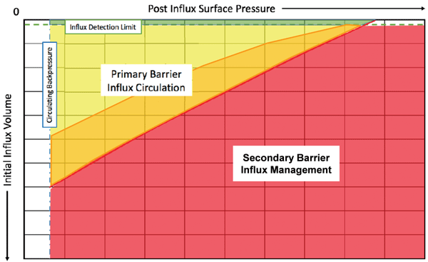
The IME concept defines the operational envelope in case of incidental influxes during MPD operations. It is based on kick tolerance concepts, in which the relationship between volume and intensity of the influx is established and plotted in a graph. A resulting combination of regions within the volume and intensity graph depicts the conditions in which an influx can be safely removed from the wellbore using elements of the primary wellbore barrier, or else the secondary wellbore barrier should be engaged and the well shut in conventionally. The regions are color coded for ease of identification during the process of managing an influx. Three regions are proposed (Figure 1):
a) The green region identifies normal MPD operations, where drilling and other operations continue as planned. No influx is detected in the wellbore, and surface pressures are within planned parameters;
b) The yellow area defines the operational region where an influx has been detected in the wellbore, and it can be safely circulated to surface within the boundaries of the primary wellbore barrier, i.e., the MPD equipment; and
c) The red zone defines the conditions in which it is deemed that some limit(s) of the primary barrier would be exceeded during the process, indicating that the well should be secured with secondary barrier envelope, i.e., BOP equipment.
Figure 1 also shows examples of how the IME can be interpreted for various influx sizes and surface influx suppression pressures.
1. Drilling operations would occur at the left-most edge of the envelope (1) at the planned circulating backpressure and overbalanced conditions.
2. The moment an influx is detected, surface pressure is increased to control the influx while maintaining pump speed. The resultant on-bottom influx volume can be calculated/reported from the MPD system, and this volume can be plotted against the post-influx surface pressure. In this example, if the post-influx volume-surface pressure pair results in a point in the yellow zone (2), the influx may be circulated to surface safely with the MPD equipment as the pressure exerted when the assumed gas influx reaches surface would be well below the primary barrier surface pressure limit.
3. If the same influx volume required a higher pressure to control (3), the surface pressure would approach the surface pressure limit once the gas bubble reaches surface. Choosing a value for the surface pressure limit with a suitable factor of safety below the dynamic pressure specification of the MPD equipment would allow for use of the MPD equipment up to this limit.
4. If the same pressure required to stop an influx as (2) resulted in a higher volume (4), the same logic as point 3 above applies; the larger influx volume could still be safely circulated to surface using the primary barrier as the resultant surface pressure would approach the surface pressure limit.
5. If the pressure required to stop an influx is the same as (2), but the resultant influx volume is larger and exceeds the IME limit (5), then the pressure exerted by the influx when it reaches surface would exceed the surface pressure limit. In effect, the primary barrier would be lost when the influx reaches surface. As such, the influx would have to be circulated using the secondary barrier. It should be stressed that at the moment the influx is controlled in state 5, the primary barrier is still intact as the surface pressures are within acceptable limits. It is only as the influx approaches surface that the barrier would be compromised.
The orange area
An additional orange zone can be added as a subset of the yellow area (Figure 2). In the orange zone, an influx can still be safely removed within the primary wellbore barrier, but one or more parameters will need to be modified to avoid exceeding some limit(s) in the process. An example would be the need to reduce the pump rate to avoid exceeding the gas flow rate through the mud-gas separator (MGS). In this case, there is no immediate risk, and the process is not severely compromised. The influx circulation can proceed at drilling rates, then divert the flow to the MGS and reduce the pump rate when the front of the influx is, for example, 1,000 m below surface.
Practical application
The IME concept was recently used in the planning of three MPD sections of a deepwater MPD well. An understanding of the governing limits was required when developing the section-specific IMEs.
The circulation limits that will dictate the boundaries between the yellow, red and orange areas in the IME should consider surface equipment and subsurface pressure limits, as well as surface flow limits.
On surface, the most common weak link is the rotating control device (RCD) pressure rating. The most common risk of exceeding the RCD pressure limit would occur later on, during the influx circulation, when the gas expands in the annulus.
The subsurface pressure limits are dictated by the expected downhole drilling window. In narrow window wells, kick tolerance may be the governing pressure. For this case study, the driving limit for IMEs in all three MPD sections was the “loss initiation pressure.” Similar to the maximum allowable annular surface pressure (MAASP) in conventional well control, this pressure applies while the influx is in the open hole. Once it has been displaced in cased hole, the constant BHP method ensures that the pressure in the open hole is constant even if the surface backpressure (SBP) exceeds the maximum limit dictated by the downhole pressure window.
IME implementation
To demonstrate how the IME was used, Figure 3 summarizes the specific approach for generating the IME for the 18 ⅛ x 22-in. hole section. Also, the maximum value for kick intensity (KI) is shown, along with the selected KIs for evaluation, with the resulting maximum influx volumes for each KI.
Figure 4 shows the calculated IME for the 18 ⅛ x 22-in. hole section, depicting orange and red zones, as well as an imposed influx limit of 20 bbl.
IME considerations for implementation
There are certain considerations regarding the IME concept that the designer and the operational team must fully understand to safely implement it:

• The IME must be clear and easy to use, with parameters that the team can easily and rapidly measure (or calculate) with information readily available during the process of managing an influx. Parameters such as pit volume totalizer (PVT), “virtual trip tank,” applied SBP and standpipe pressure provide the information necessary to read the IME.
• A specific IME should be prepared for each well section planned to be drilled using MPD. The IME should be adjusted after changes in drilling conditions and when new information becomes available, such as the formation integrity test/leak-off test. A general recommendation would be to prepare the IME for the final depth of the section, as a more conservative scenario. The MPD anchor point was established at TD of the section, as well.
• The IMEs for the project considered the capacity to stop the pumps and/or shut in the well at any time during the influx circulation process. For this, adequate calculations and use of safety margin was required.
• Although some cases allow handling higher volumes of influx safely, an arbitrary maximum limit of 20 bbl was established by the project team.
• The measured (or calculated) parameters to use on the IME must be taken at the moment of influx cessation. Using parameters measured (or calculated) at a different time may result in erroneously application of the process, potentially causing loss of well control.
• Once the decision is made to circulate an influx within the primary barrier, the operation must follow established procedures, and the IME should not be further referenced during the circulation process. Pit gain should be observed as the influx expands, and SBP should increase during constant BHP conditions, yet not related with any additional influx in the well. An attempt to continue referring to the IME during the circulation could generate confusion on the team, triggering an unnecessary shut in.
• For this well, software capable of simulating the well control process was available on the rig, both for MPD or conventional conditions, with the actual parameters measured in the eventual situation of actually taking an influx. This would allow for a comparison of real and simulated values in the event of circulating an influx with the MPD system. Discrepancies between these values could provide early indication of additional influx or another deviation in the process.

• Handing over to the secondary wellbore barrier, in the event that the IME control parameters at influx suppression exceed the yellow area limits, must follow an established procedure, which should avoid additional volume of influx by assisted shut in.
• The project team must keep in mind that the fact that the IME control parameters at influx suppression exceed the yellow area limits does not necessarily imply that there is a severe and imminent risk to the operations or safety. More likely, the situation would allow to continue dispersing the influx, and more importantly, displace it into cased hole before shutting in the well. This significantly enhances the possibilities of a successful kick circulation, minimizing the chances of breaking the shoe during the start up or the circulation process. DC
This article is based on IADC/SPE 185289, “Case Study: First Experience of Developing an Influx Management Envelope (IME) for a Deepwater MPD Operation,” at the 2017 IADC/SPE Managed Pressure Drilling and Underbalanced Operations Conference, 28-29 March, Rio de Janeiro, Brazil.
Article reference: SPE/IADC 179191, “Evolution of the MPD Operations Matrix: The Influx Management Envelope,” M.S. Culen, P.R. Brand, W. Bacon and O.R. Gabaldon, Blade Energy Partners, 2016 SPE/IADC Managed Pressure Drilling and Underbalanced Operations Conference, 12-13 April, Galveston, Texas.