Integrated sand control modeling aids GOM multizone frac-pack
Correct set-down weight on packer simulated for deepwater completion
By Hong Zhu, Kevin Joseph and Peter Chok, Baker Hughes
In sandstone reservoirs, sand control is especially vital. Unexpected sand production can lead to erosion, loss of well integrity and other safety concerns. This is particularly concerning in ultra-deepwater wells in water depths greater than 8,000 ft. There, operators work in an environment that, while offering high reward, is high profile and fraught with risks.
Long-term well integrity is one of the most important considerations in operating a deepwater well project. An operator’s financial investment, in terms of cutting-edge rigs and state-of-the-art technologies, can surpass $1 million/day. This means it is essential to fulfill the maximum potential of these wells while maintaining the highest well integrity.
Most operators choose a frac-pack completion system, which combines fracturing and gravel packing, to prevent sand production in deepwater wells. For a frac-pack operation to be successful, however, the effects on the workstring and packer must be considered during the planning stages to predict how much weight downhole is being applied to the service. The combined effects of ballooning, piston, cooling, buckling and pumping may cause large tool movement that must be offset with the set-down weight on the packer to ensure the correct relative position between the workstring and the packer.

It is critical to understand the set-down weight requirement and how that requirement affects the integrity of the packer assembly during the entire sand control operation. The hydraulics must be properly modeled because there is little direct feedback available during the operations. If the tool moves, it can cause a failure or perhaps a subpar job, which is tantamount to a failure due to the amount of money invested.
In such operations to date, the industry is still missing a way to predict what is happening during the fracturing operation – i.e., whether there is enough weight downhole. It’s a dynamic situation. If there’s a failure, the operators can lose at least an entire zone, if not the entire well.
Baker Hughes developed an integrated sand control modeling software that can support the simulation for all sand control tools and operations, including single- and multizone frac-pack and gravel-pack completions. It allows the operator to predict the function of the tool downhole during the dynamic, high-pressure phase of the multizone single-trip operations. This provides assurance that the correct weight is being applied downhole to compensate for the excessive hydraulics that may occur during the frac-pack operation.
This modeling capability has added a key dimension to the Multi-zone Single Trip (MST) frac-pack technology, which can deliver selective frac or gravel-packing treatments to multiple zones in one downhole trip.
Integrated simulations
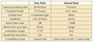
There are two major sand control operations: frac pack and gravel pack (Table 1). Gravel pack is widely used in open-hole completions, especially for long horizontal wells. In cased-hole wells, fracturing is preferred for well stimulation with sand control, which requires high treatment pressures and slurry pump rates.
The sand control modeling software integrates frac-pack and gravel-pack simulations because both make use of proppant and the crossover tool, which switches the tubing flow to the annular flow and vice
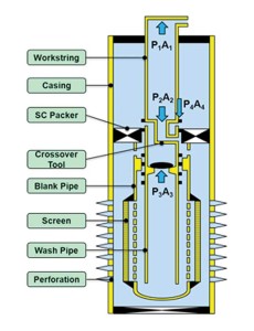
versa. They also share similar hydraulic modeling.
Figure 1 shows the sand control software capabilities. It can simulate key parameters during the sand control job, such as weight on packer, buckling effect and maximum workstring stress. It also allows for the field data collected from sand control operations to be compared with simulation results to help verify and improve the sand control modeling. The software also can be used in a post-job analysis to summarize
lessons learned.
Modeling a frac-pack operation
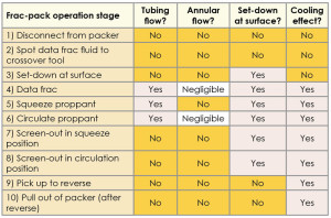
In the software, the frac-pack operation is modeled in 10 stages (Table 2): 1) Disconnect from packer; 2) Spot data frac fluid to crossover tool; 3) Set down at surface; 4) Data frac; 5) Squeeze proppant; 6) Circulate proppant; 7) Screen out in squeeze position; 8) Screen out in circulate position; 9) Pick up to reverse; and 10) Pull out of packer after reverse.
The data frac stage, also referred to as the mini frac stage, is used for calibration. During this stage, the carrier fluid without added
proppant is pumped at expected treatment rates to confirm the fluid rheology for effectively fracturing the formation. Once confirmed, the main frac treatment is finalized and performed.
Main treatment consists of the squeeze proppant and circulate proppant stages. For the squeeze stage, the top annulus is closed. For the circulating stage, also referred to as the live annulus stage, the annulus is open so that the annular pressure can be directly monitored. The screen-out happens when proppant is accumulated in the blank pipe and the pumping can no longer be continued. It marks the end of the main treatment.
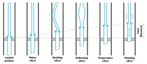
Figure 2 summarizes the flow, set-down and cooling effect for each of the frac-pack operational stages. There are five possible causes of workstring
movements during a frac-pack operation (Figure 3):
• The piston effect, caused by pressure changes inside the annulus and tubing at the packer;
• Buckling, which can present difficulty getting weight down on the frac tool to keep it in position while pumping the frac treatment;
• Ballooning, due to pressure and fluid density changes in the tubing and annulus;
• Change in temperature, which can cause major length damage in the tubing; and
• Pumping of treatment through the workstring. In the pumping, workstring roughness and turbulence
will result in pressure loss, exerting a frictional force along the tubing string, caused by pumping combined with mechanical frictional force between the workstring and casing when conducting the force calculation.
Application to deepwater multizone, frac-pack in Gulf of Mexico
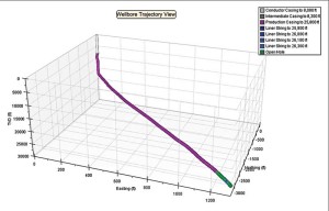
The sand control software was used in a deepwater Gulf of Mexico well to simulate planning and execution challenges of predicting workstring behavior in a frac-pack operation. The operator needed to do a frac-pack completion on two zones – the upper zone at 25,900 ft and the lower zone at 26,167 ft – and decided to use the MST frac-pack completion. Figure 4 shows the trajectory of this well.
The sand control software was used to calculate a suitable set-down weight before the main treatment, taking into account the combined effects of ballooning, thermal gradients, buckling and piston effects unique to  the MST system deployed.
One key criterion to conducting a successful frac-pack operation is to ensure that there is enough weight on the tool while maintaining the workstring stress within its limitations. Using the integrated sand control software, the decision was made to slack off 140,000 lb, which is equal to the maximum weight on the tool of 120,000 lb for the lower zone and 95,000 lb for the upper zone. With a 140,000-lb slack-off, simulation showed that it was possible to maintain 60,000-70,000 lb of weight on the tool, keeping the workstring stress within its limitation.
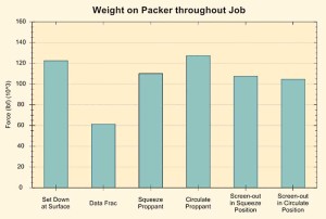
Figures 5 and 6 show the simulation results of the weight on the packer for the lower and upper zones, respectively.
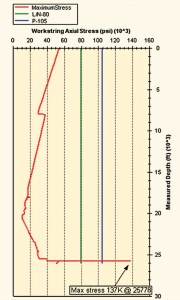
Figures 7 and 8 show the maximum stress simulation results for the lower and upper zones. Although severe buckling happened at the local workstring just above the tool in both zones, the maximum stress was still within its limit of 140,000 psi.
During the first run, a sensor was placed above the setting tool assembly to confirm the downhole weight. Although downhole tool weight data was not obtained for the entire job, the data did confirm that initially 115,000-120,000 lb were applied downhole at the lower zone. However, the sensor recorded this weight from approximately 300 ft away, and most of the buckling effects are below that point.
As the MST technology evolves, a need is recognized to have a real-time downhole weight-on-bit measurement to ensure treatment is done within the recommended pressure, temperature and stress envelopes for the service tool and the entire multizone, single-trip system.
With the success of this completion, the operator decided to use the sand control modeling software in two other multizone deepwater wells, which also were successful from a sand control perspective. Both were three-zone wells with depths of more than 26,000 ft.
Conclusions
Deepwater well completion projects, operating in dynamic environments at great costs, have huge stakes in successful production while  maintaining the long-term integrity of the well. The sand control modeling software was able to simulate the correct set-down weight downhole, which is essential to a successful sand control completion. This simulation provided a higher level of confidence for a satisfactory outcome.
Weight-on-packer simulation results were later confirmed in part by actual downhole sensors. The inner workstring pull from the job showed no sign of buckling.
Overall, the deepwater multizone, frac-pack job was a success: Two frac-pack operations were performed in one trip, complete well integrity was confirmed with all isolation packers and production packers set and tested, and minimal wear was shown on the crossover section of the service tool after more than 500,000 lb were pumped through the tool. In two subsequent jobs, both MST frac-pack completions were also successfully carried out with the aid of the software.
This article was primarily adapted from SPE 166273-MS, “Application of Sand Control Monitoring Software in Deepwater Multi-zone Frac Pack,” from the 2013 SPE Annual Technical Conference and Exhibition, New Orleans, La., 30 September to 2 October.

